omron h3cr-a8 wiring diagram
omron h3cr a8 wiring diagram - Microsoft

2022. 7. 22. · Omron H3cr A8 Wiring Diagram | Free Wiring Diagram ricardolevinsmorales.com. wiring diagram breaker box powermark gold homeline h3cr a8 center load ge omron hoist
Learn MoreOmron H3CR OFF delay Timer | OFF Delay Timer working System and
Omron H3CR OFF delay Timer.OFF Delay Timer working System and Connection diagram.Omron H3CROff delay Timer working Principle..
Learn Moreomron timer wiring diagram - Microsoft
Omron H3cr-a8 Wiring Diagram diagramweb.net. wiring h3cr a8 omron diagram timer din conforms diagramweb. H3CR Timer: Wiring Power Supply And Input Devices | FAQ | Australia www.omron.com.au. omron wiring h3cr timer faq input devices supply power incorrect example. OMRON Limit Switch Sensor Timer Counter Relay RTD Temperature uae.tradeford.com
Learn MoreSolid-state Timer H3CR

Block Diagrams. H3CR-A/AS. AC (DC) input. Power supply circuit. Zero setting detection circuit. Oscillation circuit. Time range/ unit selectors. Counting.
Learn MoreH3CR-A Solid-state Multi-functional Timers/Specifications | OMRON
The value is ±5% FS +100 ms to −0 ms max. when the C, D, or G mode signal of the H3CR-AP is OFF. *2. The influence of voltage of the H3CR-A8E (24 to 48 VAC/12 to 48 VDC) is ±2.0% FS max. with a single-phase power supply with fullwave rectification. *3. Refer to the Life-test Curve (Reference). *4. Contact output only. Life-test Curve (Reference)
Learn MoreTimer relay wiring diagram - ifbb.radschnellweg-ma-hd.de
A timer relay is a combination of an electromechanical output relay and a control circuit the contacts will open or close before or after a preselected timed.
Learn MoreMechanical Timer Omron H3CR-A8 24-48 VAC/DC - Carousell
Buy Mechanical Timer Omron H3CR-A8 24-48 VAC/DC | Omron Automation | Twin Timer | Supply Voltage | Wiring Diagram in Buhi,Philippines.
Learn MoreH3CR_A8 CAD drawing Download | OMRON Industrial Automation
2018. 1. 30. · For CAD drawing downloads, click on the link of your required format.
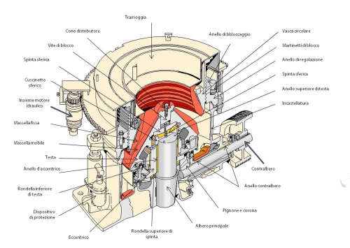
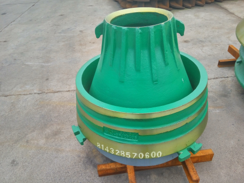
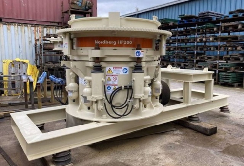
Learn MoreHP300 CONICAL HOPPER | omron h3cr-a wiring diagram
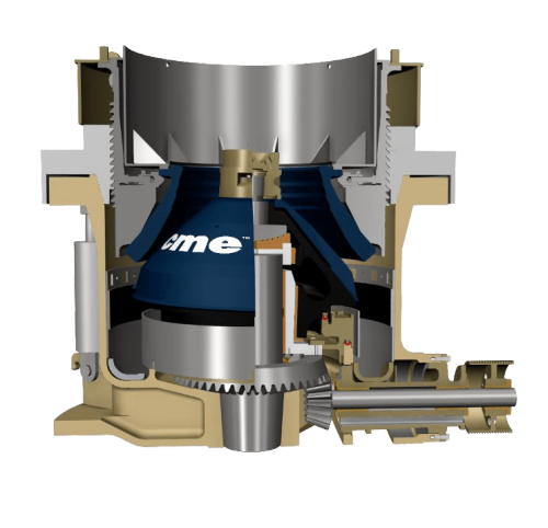
austin western crusher main shaft bushing omron h3cr troubleshooting hp4 air filter set diagram and parts roller mill sprint filter zh2. crusher wearing plate manufacturer africa omron h3cr-a8 settings skullcandy crusher spare parts oversized door hinge pin bushings skullcandy sesh evo (585b) The Use of Gas Pressure Profiles to Enhance Blending
Learn MoreNeed help wiring a Omron H3Y-2 for AC | All About Circuits
i purchased a handful of Omron H3Y-2 timers and they seem to be the correct item, Would I be better off with an Omron H3CR-A8 ?
Learn MorePDF Solid-State Timer H3CA - Digi-KeyPDF

In the schematic diagrams, each thick line indicates the external wiring necessary for the selected operation. Mode F Cycle One-Shot Power-ON Short/Power-OFF Reset The start terminals are connected. Timing starts when power is applied. The output relay will be OFF for the set time and then ON for the set time. The timer is reset when power is
Learn More
Leave a comment